5. First Steps on Hardware
This section gives a brief walk-through on setting up a debugger connection to a BMS-Master. The aim of this section is to check that all crucial parts of the toolchain work and to recap the process of setting up the toolchain.
Note
In order to be able to develop software for the BMS and deploy it to the embedded target, it is absolutely necessary to have these three components in place:
a BMS-Master,
a power supply,
a debugger.
5.1. Setup
It is assumed, that all required software has been installed as described in Software Installation.
5.2. Compilation
Details on this step are described in Building the Application. The following steps should pass and result in the application being built.
Note
TI HALCoGen is not available on Linux, and therefore the code generator
tool can not run on Linux.
Therefore, in order to build on Linux, the build process needs to be run on
Windows first, and then the entire directory
build/app_embedded/src/app/hal needs to be copied to the Linux machine.
These files should be converted to LF.
After that Linux builds are possible.
This procedure needs to be repeated everytime the HAL configuration files
(conf/hcg/app.hcg, conf/hcg/app.dil) are changed.
.\fox.ps1 waf configure build_app_embedded
./fox.sh waf configure build_app_embedded
./fox.sh waf configure build_app_embedded
If any error messages occurs, they have to be investigated before continuing.
5.3. Hardware Setup
For this first setup, it is enough to connect a power supply and a debugger to the BMS-Master. Optionally, a CAN-interface can be connected to the CAN1 connector. To debug or flash the binary file into the hardware, a debugger must also be connected to the BMS-Master. The connection is shown in Fig. 5.1 and the accompanying Table 5.1. More details on the position and type of connectors can be found in Connectors.

Fig. 5.1 BMS-Master connectors
Connector ID |
Functionality |
Pinout |
|---|---|---|
J2000 |
Smart Power Switch 0 (Contactor 0) |
|
J2001 |
Ethernet |
|
J2002 |
Smart Power Switch 1 (Contactor 1) |
|
J2003 |
Smart Power Switch 2 (Contactor 2) |
|
J2004 |
Smart Power Switch 3 (Contactor 3) |
|
J2006 |
Smart Power Switch 4 (Contactor 4) |
|
J2007 |
Smart Power Switch 5 (Contactor 5) |
|
J2008 |
Smart Power Switch 6 (Contactor 6) |
|
J2009 |
Supply |
|
J2010 |
Smart Power Switch 7 (Contactor 7) |
|
J2013 |
RS485 |
|
J2021 |
CAN 1 |
|
J2023 |
Interlock |
|
J2024 |
CAN 2 (isolated) |
|
J2023 |
Interlock |
|
J2034 |
PWM (Insulation Monitoring) |
|
J3008 |
Debugger |
|
J9000 |
Interface board |
|
J9001 |
EMIF |
|
J9002 |
Extension board |
5.4. Flash the Bootloader
In order to update the application on the fly, the bootloader needs to be compiled and flashed into the BMS-Master in advance, if it is not pre-installed on the BMS-Master. The following steps are needed to flash the bootloader:
Build the bootloader
.\fox.ps1 waf configure build_bootloader_embedded
./fox.sh waf configure build_bootloader_embedded
./fox.sh waf configure build_bootloader_embedded
Flash the binary file of the bootloader into the BMS-Master using the debugger (e.g., Lauterbach Trace32 debugger):
Connect the BMS-Master to a power supply and power it.
Launch the Lauterbach Trace32 debugger using the shortcut at
build/run_t32marm. If another debugger is used, ignore this and the next steps and follow the instructions provided for that debugger to flash the bootloader binary file into the BMS-Master.Use the “Up” button (A) to set the BMS-Master to its “Up” state and then the flash button (C) to flash the bootloader binary (see TRACE32 Power View).
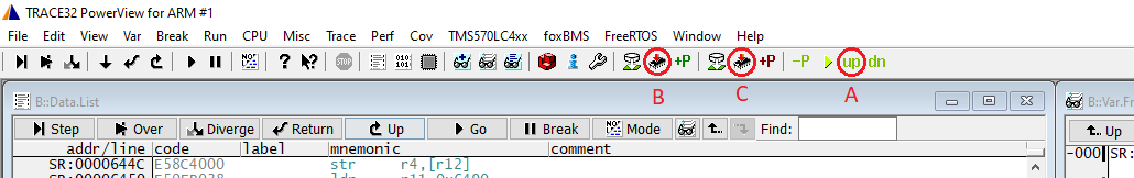
Fig. 5.2 TRACE32 Power View
The bootloader has been successfully flashed.
The bootloader now enables to flash an application binary on the BMS-Master without using a debugger.
5.5. Flash/Update the foxBMS 2 Application Using the Bootloader
Steps to flash/update the the foxBMS 2 application using the bootloader of the BMS-Master:
Connect the host PC with the BMS-Master via CAN1 using an USB to CAN adapter.
Check the connection between the host PC and the bootloader by running:
.\fox.ps1 bootloader check
./fox.sh bootloader check
./fox.sh bootloader check
If the bootloader is connected and waiting for further commands, the message Bootloader is running will be displayed:
Checking if the bootloader is online...
Bootloader is running.
Flash/update the foxBMS 2 binary into the BMS-Master:
[Option 1]: If no foxBMS binary has ever been flashed into the target:
Entering the following command in the terminal:
.\fox.ps1 bootloader load-app
./fox.sh bootloader load-app
./fox.sh bootloader load-app
The following message indicates that the foxBMS application has been successfully uploaded to the BMS-Master and should be started:
Uploading foxBMS 2 [1/3]: [▮▮▮▮▮▮▮▮▮▮▮▮▮▮▮▮▮▮▮▮▮▮▮▮▮] 100%
Successfully uploaded the application binary to the target, start the foxBMS application!
[Option 2]: If any foxBMS binary has already been flashed into the target:
Power off the BMS-Master and enter the following command in the terminal:
.\fox.ps1 bootloader load-app
./fox.sh bootloader load-app
./fox.sh bootloader load-app
Power on the BMS-Master after the following instruction is displayed in the terminal:
Waiting for the bootloader to be powered on ...
More details about the bootloader can be found in Bootloader.
5.6. Flash/Debug the Application Using the Debugger
Start the TRACE32 software using the shortcut build/run_t32marm.lnk
that is generated during project configuration (only generated if Lauterbach is
available), and click the “Up” button (A) to set the BMS-Master to its
Up state.
After that, click the application flash button (B) to flash the foxBMS 2
application and bootloader flash button (C) to flash the embedded
bootloader.
Fig. 5.3 Lauterbach TRACE32 UI to flash the embedded software
After the binary is successfully flashed, the user can start the application and debug it using the features of the debugger software. More details on setting up the debugger toolchain can be found in Debugging the Application.
