 |
foxBMS
1.6.0
The foxBMS Battery Management System API Documentation
|
|
foxBMS
1.6.0
The foxBMS Battery Management System API Documentation
|
Header for the configuration for the LTC 6804-1 6811-1, 6812-1, and 6813-1 monitoring IC. More...
#include "ltc_cfg.h"#include "ltc_defs.h"#include "battery_system_cfg.h"#include "ltc_afe_dma.h"#include "spi.h"#include <stdbool.h>#include <stdint.h>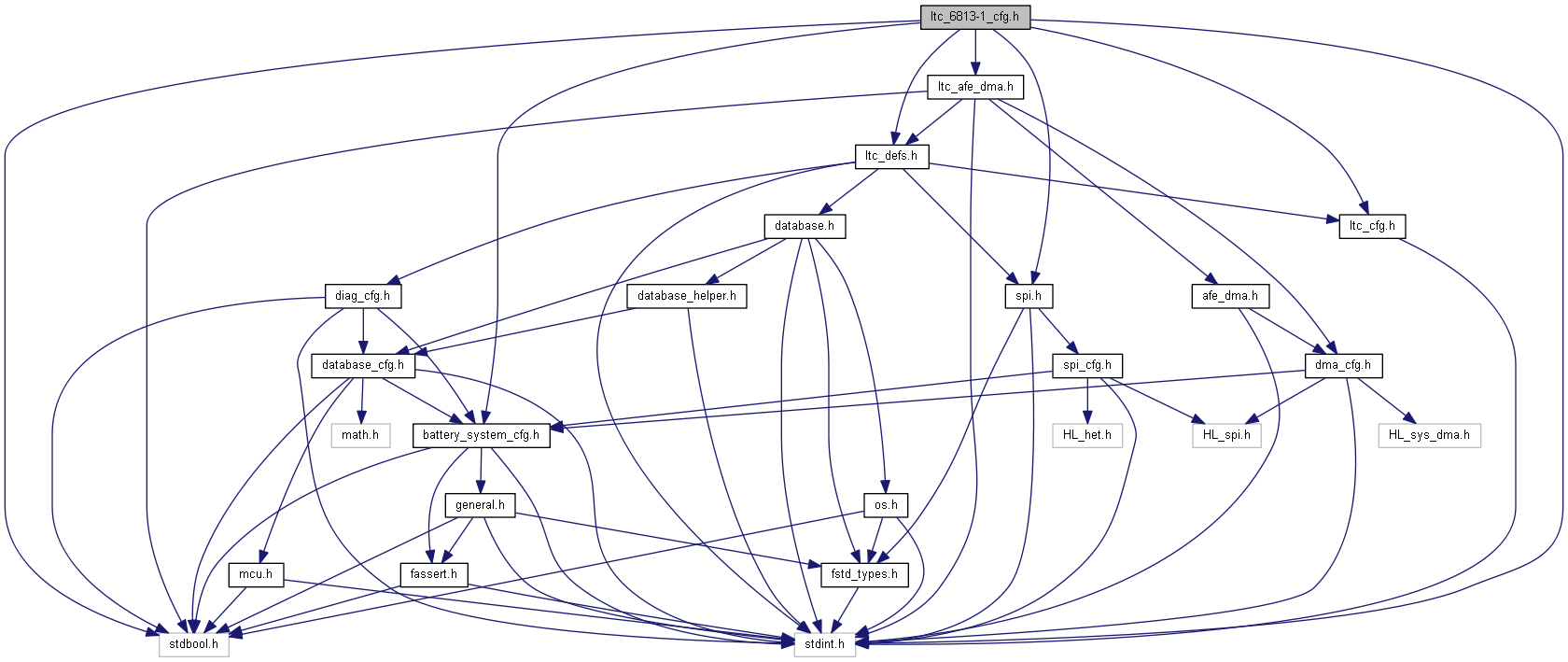
Go to the source code of this file.
Functions | |
| int16_t | LTC_ConvertMuxVoltagesToTemperatures (uint16_t adcVoltage_mV) |
| converts a raw voltage from multiplexer to a temperature value in deci °C. More... | |
Variables | |
| LTC_MUX_SEQUENCE_s | ltc_mux_seq |
| const uint8_t | ltc_muxsensortemperatur_cfg [BS_NR_OF_TEMP_SENSORS_PER_MODULE] |
| const uint8_t | ltc_voltage_input_used [LTC_6813_MAX_SUPPORTED_CELLS] |
Header for the configuration for the LTC 6804-1 6811-1, 6812-1, and 6813-1 monitoring IC.
SPDX-License-Identifier: BSD-3-Clause
Redistribution and use in source and binary forms, with or without modification, are permitted provided that the following conditions are met:
THIS SOFTWARE IS PROVIDED BY THE COPYRIGHT HOLDERS AND CONTRIBUTORS "AS IS" AND ANY EXPRESS OR IMPLIED WARRANTIES, INCLUDING, BUT NOT LIMITED TO, THE IMPLIED WARRANTIES OF MERCHANTABILITY AND FITNESS FOR A PARTICULAR PURPOSE ARE DISCLAIMED. IN NO EVENT SHALL THE COPYRIGHT HOLDER OR CONTRIBUTORS BE LIABLE FOR ANY DIRECT, INDIRECT, INCIDENTAL, SPECIAL, EXEMPLARY, OR CONSEQUENTIAL DAMAGES (INCLUDING, BUT NOT LIMITED TO, PROCUREMENT OF SUBSTITUTE GOODS OR SERVICES; LOSS OF USE, DATA, OR PROFITS; OR BUSINESS INTERRUPTION) HOWEVER CAUSED AND ON ANY THEORY OF LIABILITY, WHETHER IN CONTRACT, STRICT LIABILITY, OR TORT (INCLUDING NEGLIGENCE OR OTHERWISE) ARISING IN ANY WAY OUT OF THE USE OF THIS SOFTWARE, EVEN IF ADVISED OF THE POSSIBILITY OF SUCH DAMAGE.
We kindly request you to use one or more of the following phrases to refer to foxBMS in your hardware, software, documentation or advertising materials:
Definition in file ltc_6813-1_cfg.h.
| #define LTC_6813_MAX_SUPPORTED_CELLS (18u) |
Defines the maximal number of supported cells per module.
Definition at line 90 of file ltc_6813-1_cfg.h.
| #define LTC_ADOW_THRESHOLD (-400) |
Open-wire detection threshold
Definition at line 130 of file ltc_6813-1_cfg.h.
| #define LTC_DISCARD_MUX_CHECK (false) |
Definition at line 112 of file ltc_6813-1_cfg.h.
| #define LTC_DISCARD_PEC (false) |
Controls if PEC should be discarded (true) or not (false)
Definition at line 106 of file ltc_6813-1_cfg.h.
| #define LTC_GOTO_MUX_CHECK (true) |
Definition at line 109 of file ltc_6813-1_cfg.h.
| #define LTC_GPIO_MEASUREMENT_MODE (LTC_ADCMODE_NORMAL_DCP0) |
Measurement modus for GPIOs, possible values:
Definition at line 146 of file ltc_6813-1_cfg.h.
| #define LTC_N_MUX_CHANNELS_PER_LTC (LTC_N_MUX_PER_LTC * LTC_N_MUX_CHANNELS_PER_MUX) |
Number of multiplexed channels per LTC-IC
Definition at line 124 of file ltc_6813-1_cfg.h.
| #define LTC_N_MUX_CHANNELS_PER_MUX (8u) |
Number of channels per multiplexer
Definition at line 118 of file ltc_6813-1_cfg.h.
| #define LTC_N_MUX_PER_LTC (3u) |
Number of multiplexer used per LTC-IC
Definition at line 115 of file ltc_6813-1_cfg.h.
| #define LTC_NMBR_REQ_ADOW_COMMANDS (2) |
Number of required ADOW commands because of external C-Pin capacitance and the respective duration to perform an open wire check for 14 modules with 12 cells each. During this time no cell voltages and temperatures are measured! +-------------—+-----------—+------------—+-------—+-------—+ | External C pin | Normal mode | Filtered mode | Duration | Duration | | capacitance | | | normal | filtered | | ------------—+-----------—+------------—+-------—+-------—+ | <= 10nF | 2 | 2 | 32ms | 828ms | | 100nF | 10 | 2 | 112ms | 828ms | | 1uF | 100 | 2 | 1012ms | 828ms | | C | 1.5+(C/10nF) | 2 | | | +-------------—+-----------—+------------—+-------—+-------—+
Definition at line 308 of file ltc_6813-1_cfg.h.
| #define LTC_NUMBER_OF_LTC_PER_MODULE (1u) |
Number of LTC-ICs per battery module
Definition at line 127 of file ltc_6813-1_cfg.h.
| #define LTC_NUMBER_OF_MUX_MEASUREMENTS_PER_CYCLE (8u) |
Number of multiplexer measurements per LTC cycle
Definition at line 121 of file ltc_6813-1_cfg.h.
| #define LTC_OW_MEASUREMENT_MODE (LTC_ADCMODE_NORMAL_DCP0) |
Measurement modus for Open-wire check, possible values:
Definition at line 153 of file ltc_6813-1_cfg.h.
| #define LTC_PORTEXPANDER_ADR_TI (0u) |
Address of TI port expander (0 or 1)
Definition at line 103 of file ltc_6813-1_cfg.h.
| #define LTC_PORTEXPANDER_VERSION (1u) |
If set to 0 LTC driver is configured to use PCA8574 port expander If set to 1 LTC driver is configured to use TCA6408A port expander
Definition at line 100 of file ltc_6813-1_cfg.h.
| #define LTC_READCOM (0) |
If set to 1, check if multiplexers acknowledged transmission
Definition at line 292 of file ltc_6813-1_cfg.h.
| #define LTC_SPI_HANDLE (&spi_devices[0]) |
SPI1 is used for communication with LTC
Definition at line 165 of file ltc_6813-1_cfg.h.
| #define LTC_SPI_INSTANCE (*LTC_SPI_HANDLE.Instance) |
SPI1 is used for communication with LTC
Definition at line 166 of file ltc_6813-1_cfg.h.
| #define LTC_SPI_PRESCALER (*LTC_SPI_HANDLE.Init.BaudRatePrescaler) |
SPI1 is used for communication with LTC
Definition at line 167 of file ltc_6813-1_cfg.h.
| #define LTC_SPI_WAKEUP_WAIT_TIME_US (30u) |
LTC SPI wakeup time
Definition at line 178 of file ltc_6813-1_cfg.h.
| #define LTC_STATEMACH_DAISY_CHAIN_FIRST_INITIALIZATION_TIME ((LTC_TWAKE_US * LTC_N_LTC) / 1000) |
time for the first initialization of the daisy chain see LTC6804 data sheet page 41
Definition at line 187 of file ltc_6813-1_cfg.h.
| #define LTC_STATEMACH_DAISY_CHAIN_SECOND_INITIALIZATION_TIME ((LTC_TREADY_US * LTC_N_LTC) / 1000) |
time for the second initialization of the daisy chain see LTC6804 data sheet page 41
Definition at line 192 of file ltc_6813-1_cfg.h.
| #define LTC_STATEMACH_MEAS_ALL_CELLS_FAST_TCYCLE (2) |
~1.1ms Measurement+Calibration Cycle Time When Starting from the REFUP State in Fast Mode unit: ms
Definition at line 202 of file ltc_6813-1_cfg.h.
| #define LTC_STATEMACH_MEAS_ALL_CELLS_FILTERED_TCYCLE (202) |
~201ms Measurement+Calibration Cycle Time When Starting from the REFUP State in Filtered Mode unit: ms
Definition at line 214 of file ltc_6813-1_cfg.h.
| #define LTC_STATEMACH_MEAS_ALL_CELLS_NORMAL_TCYCLE (3) |
~2.3ms Measurement+Calibration Cycle Time When Starting from the REFUP State in Normal Mode unit: ms
Definition at line 208 of file ltc_6813-1_cfg.h.
| #define LTC_STATEMACH_MEAS_ALL_GPIOS_FAST_TCYCLE (2) |
~1.8ms Measurement+Calibration Cycle Time When Starting from the REFUP State in Fast Mode unit: ms
Definition at line 242 of file ltc_6813-1_cfg.h.
| #define LTC_STATEMACH_MEAS_ALL_GPIOS_FILTERED_TCYCLE (336) |
~335ms Measurement+Calibration Cycle Time When Starting from the REFUP State in Filtered Mode unit: ms
Definition at line 254 of file ltc_6813-1_cfg.h.
| #define LTC_STATEMACH_MEAS_ALL_GPIOS_NORMAL_TCYCLE (4) |
~3.9ms Measurement+Calibration Cycle Time When Starting from the REFUP State in Normal Mode unit: ms
Definition at line 248 of file ltc_6813-1_cfg.h.
| #define LTC_STATEMACH_MEAS_SINGLE_GPIO_FAST_TCYCLE (1) |
~380us Measurement+Calibration Cycle Time When Starting from the REFUP State in Fast Mode unit: ms
Definition at line 260 of file ltc_6813-1_cfg.h.
| #define LTC_STATEMACH_MEAS_SINGLE_GPIO_FILTERED_TCYCLE (68) |
~67.1ms Measurement+Calibration Cycle Time When Starting from the REFUP State in Filtered Mode unit: ms
Definition at line 272 of file ltc_6813-1_cfg.h.
| #define LTC_STATEMACH_MEAS_SINGLE_GPIO_NORMAL_TCYCLE (1) |
~788us Measurement+Calibration Cycle Time When Starting from the REFUP State in Normal Mode unit: ms
Definition at line 266 of file ltc_6813-1_cfg.h.
| #define LTC_STATEMACH_MEAS_TWO_CELLS_FAST_TCYCLE (1) |
~203us Measurement+Calibration Cycle Time When Starting from the REFUP State in Fast Mode unit: ms
Definition at line 220 of file ltc_6813-1_cfg.h.
| #define LTC_STATEMACH_MEAS_TWO_CELLS_FILTERED_TCYCLE (35) |
~34ms Measurement+Calibration Cycle Time When Starting from the REFUP State in Filtered Mode unit: ms
Definition at line 232 of file ltc_6813-1_cfg.h.
| #define LTC_STATEMACH_MEAS_TWO_CELLS_NORMAL_TCYCLE (1) |
~407us Measurement+Calibration Cycle Time When Starting from the REFUP State in Normal Mode unit: ms
Definition at line 226 of file ltc_6813-1_cfg.h.
| #define LTC_STATEMACH_PECERRTIME (1) |
LTC state machine CRC-transmission error timing in ms
Definition at line 277 of file ltc_6813-1_cfg.h.
| #define LTC_STATEMACH_SEQERRTTIME (5) |
LTC state machine sequence error timing in ms
Definition at line 275 of file ltc_6813-1_cfg.h.
| #define LTC_STATEMACH_SHORTTIME (1) |
LTC state machine short time definition in ms
Definition at line 181 of file ltc_6813-1_cfg.h.
| #define LTC_TIDLE_US (6700) |
start definition of LTC timings; Tidle (see LTC data sheet)
Definition at line 175 of file ltc_6813-1_cfg.h.
| #define LTC_TRANSMISSION_TIMEOUT (10) |
Timeout in milliseconds added to the transmission time for interrupt-based SPI transmission.
Definition at line 159 of file ltc_6813-1_cfg.h.
| #define LTC_TRANSMIT_COMMAND | ( | spi_ltcInterface, | |
| command | |||
| ) |
Transmit functions
Definition at line 318 of file ltc_6813-1_cfg.h.
| #define LTC_TRANSMIT_I2C_COMMAND | ( | spi_ltcInterface, | |
| txbuf | |||
| ) |
Transmit functions
Definition at line 315 of file ltc_6813-1_cfg.h.
| #define LTC_TRANSMIT_PECERRLIMIT (10) |
Maximum number of re-tries in case of CRC error during the communication with daisy chain before going into error state
Definition at line 283 of file ltc_6813-1_cfg.h.
| #define LTC_TRANSMIT_RECEIVE_DATA | ( | spi_ltcInterface, | |
| txbuf, | |||
| rxbuf, | |||
| length | |||
| ) |
Transmit functions
Definition at line 321 of file ltc_6813-1_cfg.h.
| #define LTC_TRANSMIT_SPIERRLIMIT (3) |
Maximum number of re-tries in case of SPI error during the communication with daisy chain before going into error state
Definition at line 289 of file ltc_6813-1_cfg.h.
| #define LTC_TRANSMIT_WAKE_UP | ( | spi_ltcInterface | ) | SPI_TransmitDummyByte(spi_ltcInterface, LTC_SPI_WAKEUP_WAIT_TIME_US) |
Transmit functions
Definition at line 314 of file ltc_6813-1_cfg.h.
| #define LTC_TREADY_US (10) |
start definition of LTC timings; Tready (see LTC data sheet)
Definition at line 173 of file ltc_6813-1_cfg.h.
| #define LTC_TWAKE_US (300) |
start definition of LTC timings; Twake (see LTC data sheet)
Definition at line 171 of file ltc_6813-1_cfg.h.
| #define LTC_VOLTAGE_MEASUREMENT_MODE (LTC_ADCMODE_NORMAL_DCP0) |
Measurement modus for voltages, possible values:
Definition at line 138 of file ltc_6813-1_cfg.h.
| #define SLAVE_BOARD_VERSION (2) |
If set to 1 LTC driver is configured to use foxBMS slave boards version 1.x If set to 2 LTC driver is configured to use foxBMS slave boards version 2.x
Definition at line 78 of file ltc_6813-1_cfg.h.
| int16_t LTC_ConvertMuxVoltagesToTemperatures | ( | uint16_t | adcVoltage_mV | ) |
converts a raw voltage from multiplexer to a temperature value in deci °C.
The temperatures are read from NTC elements via voltage dividers. This function implements the look-up table between voltage and temperature, taking into account the NTC characteristics and the voltage divider.
| adcVoltage_mV | voltage read from the multiplexer in mV |
Definition at line 232 of file ltc_6813-1_cfg.c.
|
extern |
Definition of the multiplexer measurement sequence
Definition at line 182 of file ltc_6813-1_cfg.c.
|
extern |
On the foxBMS slave board there are 6 multiplexer inputs dedicated to temperature sensors by default. Lookup table between temperature sensors and battery cells
Definition at line 186 of file ltc_6813-1_cfg.c.
|
extern |
Lookup table to indicate which voltage inputs are used
Definition at line 66 of file ltc_6806_cfg.c.
 1.9.1
1.9.1 