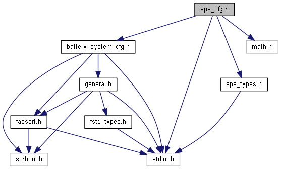
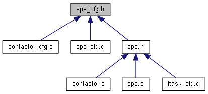
Header for the configuration for the driver for the smart power switches.
- Copyright
- © 2010 - 2023, Fraunhofer-Gesellschaft zur Foerderung der angewandten Forschung e.V. All rights reserved.
SPDX-License-Identifier: BSD-3-Clause
Redistribution and use in source and binary forms, with or without modification, are permitted provided that the following conditions are met:
- Redistributions of source code must retain the above copyright notice, this list of conditions and the following disclaimer.
- Redistributions in binary form must reproduce the above copyright notice, this list of conditions and the following disclaimer in the documentation and/or other materials provided with the distribution.
- Neither the name of the copyright holder nor the names of its contributors may be used to endorse or promote products derived from this software without specific prior written permission.
THIS SOFTWARE IS PROVIDED BY THE COPYRIGHT HOLDERS AND CONTRIBUTORS "AS IS" AND ANY EXPRESS OR IMPLIED WARRANTIES, INCLUDING, BUT NOT LIMITED TO, THE IMPLIED WARRANTIES OF MERCHANTABILITY AND FITNESS FOR A PARTICULAR PURPOSE ARE DISCLAIMED. IN NO EVENT SHALL THE COPYRIGHT HOLDER OR CONTRIBUTORS BE LIABLE FOR ANY DIRECT, INDIRECT, INCIDENTAL, SPECIAL, EXEMPLARY, OR CONSEQUENTIAL DAMAGES (INCLUDING, BUT NOT LIMITED TO, PROCUREMENT OF SUBSTITUTE GOODS OR SERVICES; LOSS OF USE, DATA, OR PROFITS; OR BUSINESS INTERRUPTION) HOWEVER CAUSED AND ON ANY THEORY OF LIABILITY, WHETHER IN CONTRACT, STRICT LIABILITY, OR TORT (INCLUDING NEGLIGENCE OR OTHERWISE) ARISING IN ANY WAY OUT OF THE USE OF THIS SOFTWARE, EVEN IF ADVISED OF THE POSSIBILITY OF SUCH DAMAGE.
We kindly request you to use one or more of the following phrases to refer to foxBMS in your hardware, software, documentation or advertising materials:
- ″This product uses parts of foxBMS®″
- ″This product includes parts of foxBMS®″
- ″This product is derived from foxBMS®″
- Author
- foxBMS Team
- Date
- 2020-10-14 (date of creation)
- Updated
- 2023-10-12 (date of last update)
- Version
- v1.6.0
- Prefix
- SPS
Definition in file sps_cfg.h.

 1.9.1
1.9.1 